Pegasus
Vehicle Design
Overall Vehicle

Pegasus XL
Length: 16.9m (55.4 ft)
Gross Liftoff Mass: 23 t (51 klbm)
Thrust at Launch: 726 kN (163 klbf)

HAPS stage
Stages 1–3 and HAPS
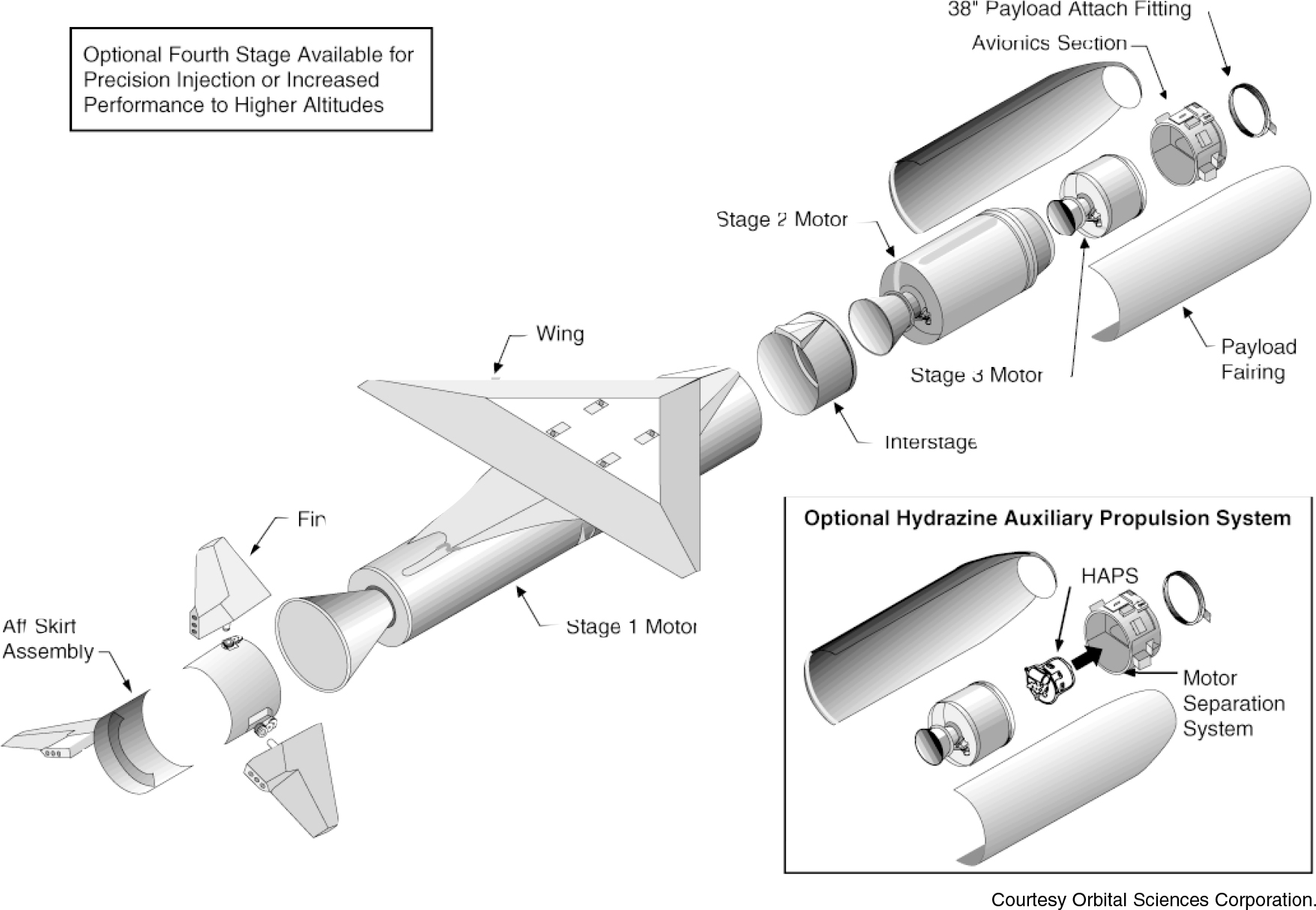
The first stage of Pegasus consists of an Orion solid motor, a delta planform composite wing, and an aft skirt assembly with three composite aerodynamic control fins. The Orion family of motors was developed by Hercules (now part of Alliant Techsystems) as part of a joint venture with Orbital for the Pegasus program. The motors have been developed using a conservative design philosophy that includes the use of demonstrated component technology, maximum use of common components and tooling among stages, and the use of class 1.3 propellant. The original Orion 50S motor was stretched to accommodate 24% more propellant for the Pegasus XL vehicle.
The wing configuration is a truncated delta planform with a 45-deg sweptback leading edge and a 6.7-m (22-ft) span. The airfoil is a double wedge. The wing and fins are fabricated of lightweight graphite composite sheets over Nomex foam cores. Graphite wing spars carry the wing load, and aluminum spars in the wing box support the booster while it is attached to the carrier aircraft. The aluminum aft structure supports the three active fins, associated electromechanical fin actuators, and high-voltage battery system. The fins provide aerodynamic control of the vehicle attitude during atmospheric flight. The two horizontal fins were changed on the Pegasus XL to a more anhedral orientation to provide clearance for the landing gear of the L1011 carrier aircraft.
The second-stage motor is very similar in design to the first-stage motor and includes a similar core burning grain and forward dome igniter. A flight termination charge is mounted on the aft dome of each motor to satisfy both range safety and aircraft safety requirements. If initiated, it cuts through the graphite case, insulation, and propellant, compromising the structural integrity of the motor. The Orion 50XL motor contains 30% more propellant than the Orion 50 used on the original Pegasus and Taurus boosters.
The third-stage motor incorporates a head–end grain design to maximize propellant density. The third stage also uses a flexseal nozzle and electromechanical actuators for TVC and employs a toroidal igniter. The third-stage Orion 38 motor has not been stretched from the original Pegasus configuration.
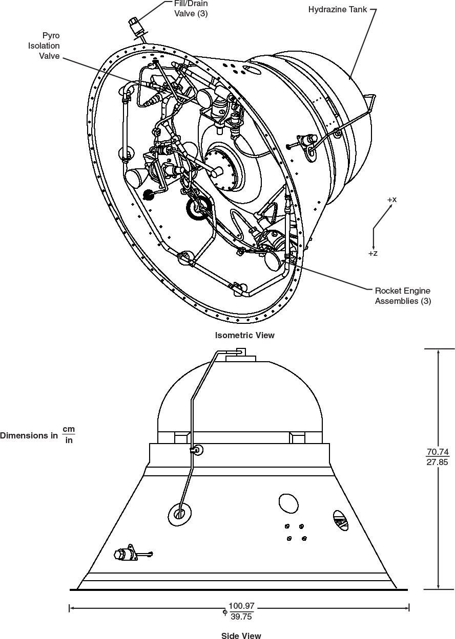
There is an optional liquid fourth stage for the Pegasus XL, the HAPS. The HAPS (now in its third generation) uses a hydrazine propulsion subsystem located inside the existing avionics deck to increase launch vehicle accuracy and improve performance above an altitude of 600 km (320 nmi). The system uses three axially directed thrusters for propulsion and off-pulses to provide pitch and yaw control. Roll control uses the existing cold-gas reaction control system.
The inert mass shown for Stage 1 reflects only the motor itself and the attached wing saddle, truss, and fasteners. The wing structure weighs an additional 285 kg (630 lbm), while the mass of the aft skirt assembly with the tail fins is unknown.
Stage 1 Orion 50SXL | Stage 2 Orion 50XL | Stage 3 Orion 38 | Stage 4 HAPS (Optional) | |
Dimensions | ||||
Length | 10.3 m (33.8 ft) | 3.11 m (10.2 ft) | 1.34 m (4.4 ft) | 0.71 m (2.3 ft) |
Diameter | 1.28 m (4.2 ft) | 1.28 m (4.2 ft) | 1 m (3.2 ft) | 1.0 m (3.3 ft) |
Mass | ||||
Propellant Mass | 15,000 kg (33,100 lbm) | 3915 kg (8633 lbm) | 770 kg (1697 lbm) | 59 kg (130 lbm) |
Inert Mass | 1340 kg (3019 lbm) | 416 kg (918 lbm) | 410 kg (900 lbm) | 22 kg (50 lbm) |
Gross Mass | 16,400 kg (36,100 lbm) | 4331 kg (9551 lbm) | 1180 kg (2600 lbm) | ? |
Propellant Mass Fraction | 0.91 | 0.90 | 0.65 | |
Structure | ||||
Type | Motor: Filament-wound monocoque Wing and Fins: composite–foam sandwich | Filament-wound monocoque | Filament-wound monocoque | Monocoque |
Material | Motor: Graphite-epoxy composite | Graphite–epoxy composite | Graphite–epoxy composite | Tank: titanium |
Propulsion | ||||
Engine Designation | Orion 50S-XL(Alliant Techsystems) | Orion 50-XL(Alliant Techsystems) | Orion 38 (Alliant Techsystems) | MR-107 (Aerojet) |
Number of Engines | 1 (1 segment) | 1 (1 segment) | 1 (1 segment) | 3 |
Propellant | HPTB | HTPB | HTPB | Hydrazine |
Average Thrust | 594 kN (133.5 klbf) | 153 kN (34.5 klbf) | 47.2 kN (10.6 k lbf) | Approximately 220 N (50 lbf) each |
Isp | 295 s | 289 s | 287 s | Approximately 225 s |
Chamber Pressure | 7515 kPa (1090 psi) | 7026 kPa (1019 psi) | 4523 kPa (656 psi) | ? |
Nozzle Expansion Ratio | 39.5:1 | 58.6:1 | 67.5:1 | ? |
Restart Capability | None | None | None | Yes |
Tank Pressurization | — | — | — | Helium |
Attitude Control | ||||
Pitch and Yaw | Three electromechanically actuated aerodynamic fins | Electromechanical nozzle gimbaling ±3 deg | Electromechanical nozzle gimbaling, ±3 deg | Thruster pulsing |
Roll | Three electromechanically actuated aerodynamic fins | Nitrogen cold-gas RCS | Nitrogen cold-gas RCS | Nitrogen cold-gas RCS |
Staging | ||||
Nominal Burn Time | 68.6 s | 69.4 s | 68.5 s | Variable |
Shutdown Process | Burn to depletion | Burn to depletion | Burn to depletion | Command shut down |
Stage Separation | Linear-shaped charge | Linear-shaped charge | Marmon clamp | Marmon clamp |
Attitude Control System
The Pegasus ACS is fully autonomous. A combination of open-loop steering and closed-loop guidance is employed during the flight. First-stage guidance utilizes a pitch profile optimized using simulations. The fins, mounted on the Pegasus first stage, aerodynamically provide pitch, yaw, and roll control during the first-stage powered flight and the coast period after burnout. During this stage, the vehicle attitude is controlled by the fin actuator system (FAS), which consists of electrically actuated fins located at the aft end of the first stage. Guidance for the second and third stages uses an adaptation of an algorithm that was first developed for the Space Shuttle ascent guidance. Electrically activated thrust vector controllers on the second- and third-stage nozzles control pitch and yaw attitudes. A gaseous nitrogen reaction control system, located forward of the third stage, is used to provide roll control throughout second- and third-stage flight. The cold-gas reaction system is also employed in every coast period to maintain three-axis control. The payload fairing provides openings for the two pods of the RCS thrusters so that reaction control is available before payload fairing separation. The exact sequence of attitude and guidance modes during a flight is controlled by the mission data load (MDL) software and depends upon mission specific requirements. Following orbital insertion, the Pegasus third stage executes a series of prespecified commands contained in the MDL to provide the desired initial payload attitude before payload separation. An inertially fixed, sun-pointing or spin-stabilized attitude may be specified. For inertial attitudes the payload and third stage or the payload and HAPS can be oriented to better than ±3 deg in angular position in each axis. Sun-pointing attitudes can be achieved to an accuracy of 4 deg. For a spin-stabilized initial attitude, the maximum spin rate achievable depends on the payload and spent third stage combined spin-axis moment of inertia.
Avionics
The Pegasus avionics system is a digital distributed processor design. Mission reliability is achieved by using simple designs, high-reliability components, high design margins, and extensive testing at the subsystem and system level. The core of the Pegasus avionics system is a multiprocessor, 32-bit flight computer. The flight computer communicates with the IMU, the launch panel electronics on the carrier aircraft, and all vehicle subsystems using standard RS-422 digital serial data links. Most avionics on the vehicle feature integral microprocessors to perform local processing and to handle communications with the flight computer. This RS-422 architecture enables more efficient integration and test, as it allows unit and system-level testing to be accomplished using commercially available ground support equipment with off-the-shelf hardware.
The avionics subsystem is mounted to the third-stage motor and serves as a mounting structure for most vehicle avionics. These include an IMU, flight computer, telemetry transmitter, telemetry multiplexer, ordnance and thruster driver units, RCS thrusters, dual flight termination receivers, radar transponder, batteries, various other components, and the harness. The structure is composed of a graphite cylindrical section. The avionics structure also provides the mechanical interface for the payload.
Pegasus is controlled by the multiprocessor 32-bit flight computer, which communicates via serial interfaces with individual microprocessors in the vehicle’s smart actuator and sensor assemblies. These distributed microprocessors manage the actuators, ordnance initiation devices, and telemetry data-gathering systems, including initialization, self-test, and health reporting via telemetry.
The telemetry system doubles as a ground checkout unit. During flight all critical vehicle performance parameters are transmitted to the ground using two S-band telemetry channels. A C-band radar transponder is provided to improve the ability of ground stations to track the vehicle during ascent. A fully redundant UHF flight termination system is provided to satisfy range safety requirements. Antenna systems for these three RF links are installed on both the second- and third-stage motors. The electrical power system on Pegasus consists of two individual battery and power distribution subsystems.
The electronic airborne support equipment (ASE) for the Pegasus is contained in a single pallet onboard the L-1011 carrier aircraft. The ASE controls the aircraft power supply interface to the launch vehicle, downloads mission data to the vehicle flight computer, enables the vehicle for drop, and provides reference data for the vehicle IMU alignment. The Pegasus flight computer controls microprocessors to manage actuators, ordnance initiation devices, and telemetry data-gathering systems. Two IMUs are used in conducting a Pegasus flight. The vehicle contains an IMU internally that is initialized in flight by a precision IMU carried in the carrier aircraft’s ASE.
Payload Fairing
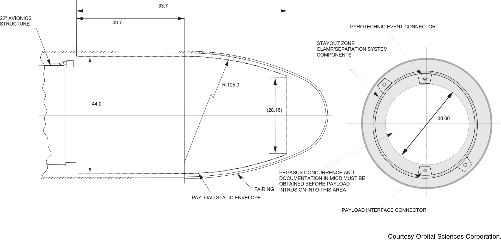
The payload fairing consists of a two-piece carbon–composite shell structure, a nose cap integral to one of the shell halves, and a separation system. The fairing maintains the 1.27 m (50 in.) outside diameter of the second-stage motor and completely encloses the smaller diameter third-stage motor, payload, and avionics subsystem. Openings are provided for two sets of RCS thruster pods, payload access doors as required, and pyrotechnic bolt cutters for separation of the fairing clamp rings. Pressure-relief cutouts near the base of the fairing provide bulk venting. When on the ground and during captive flight, the payload area is cooled and maintained under positive pressurization by an air conditioning system. During an abort or in response to special payload requirements, dry gaseous nitrogen can be purged through the fairing from tanks inside the L-1011 carrier aircraft.
Each shell half is composed of a cylinder and ogive sections, which are held together with two titanium straps along the cylinder and a retention bolt in the nose. A cork and room temperature vulcanizing thermal protection system provides protection to the graphite–composite fairing structure. The amount applied has been determined to optimize fairing performance and payload environment protection. The two straps are tensioned using bolts, which are severed during fairing separation with pyrotechnic bolt cutters, while the retention bolt in the nose is released with a pyrotechnic separation nut. The base of the fairing is retained with Orbital’s low-contamination frangible separation joint. These ordnance events are sequenced for proper separation dynamics. A hot-gas generator internal to the fairing is also activated at separation to pressure two piston-driven push-off thrusters. These units, in conjunction with cams, force the two fairing halves apart. The halves rotate about fall-away hinges, which guide them away from the satellite and launch vehicle. The fairing and separation system are qualified through a series of structural, functional, and contamination ground vacuum tests and have been successfully flown on all Pegasus XL missions.
Static Envelope

Length: 4.42 m (14.5 ft)
Primary Diameter: 1.27 m (4.16 ft)
Mass: 170 kg (373 lbm)
Sections: Two shell halves
Structure: Carbon–composite shell structure