Ariane
Vehicle Design
Overall Vehicle
Ariane 5
Height
AR5ECA 52.0 m (171 ft)
Gross Liftoff Mass
AR5ECA 780 t (1720 klbm)
Thrust at Liftoff
AR5ECA 15.12 MN (3399 klbf)
Ariane 6
Height
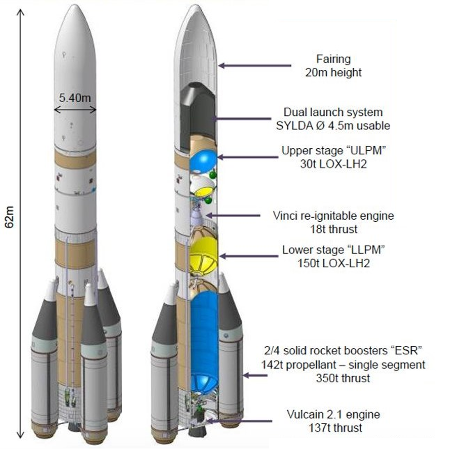
AR6 63.0 m (207 ft)
Gross Liftoff Mass
AR62 530 t (1170 klbm)
AR64 860 t (1900 klb)
Thrust at Liftoff
AR 62 10.37 MN (2331 klbf)
AR 64 19.37 MN (4355 klbf)
Ariane 5 Stages
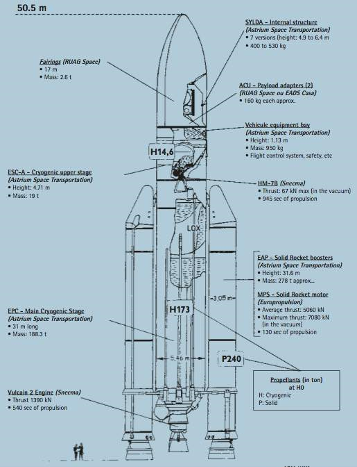
Most of Ariane 5’s liftoff thrust is provided by two EAP P241 solid boosters, which use large segmented solid motors designated MPS. The motors are a sig-nificant technical advance for ESA, being about 10 times larger than previous European solid motors. The motors are made of seven casing sections that are combined to make three propellant segments. The large central and lower segments are cast on site at the CSG Space Center, while the small forward igniter segment is cast in Italy. The three separate segments are integrated using two field joints during vehicle integration. The thrust profile of the boosters includes reduced thrust during the period of maximum dynamic pressure, so that the first stage engine does not need to be throttled. On occasional flights, a recovery system consisting of six parachutes is installed in the nose cone of each booster. The boosters are not intended to be reused, but recovery permits inspection of the motors after use.
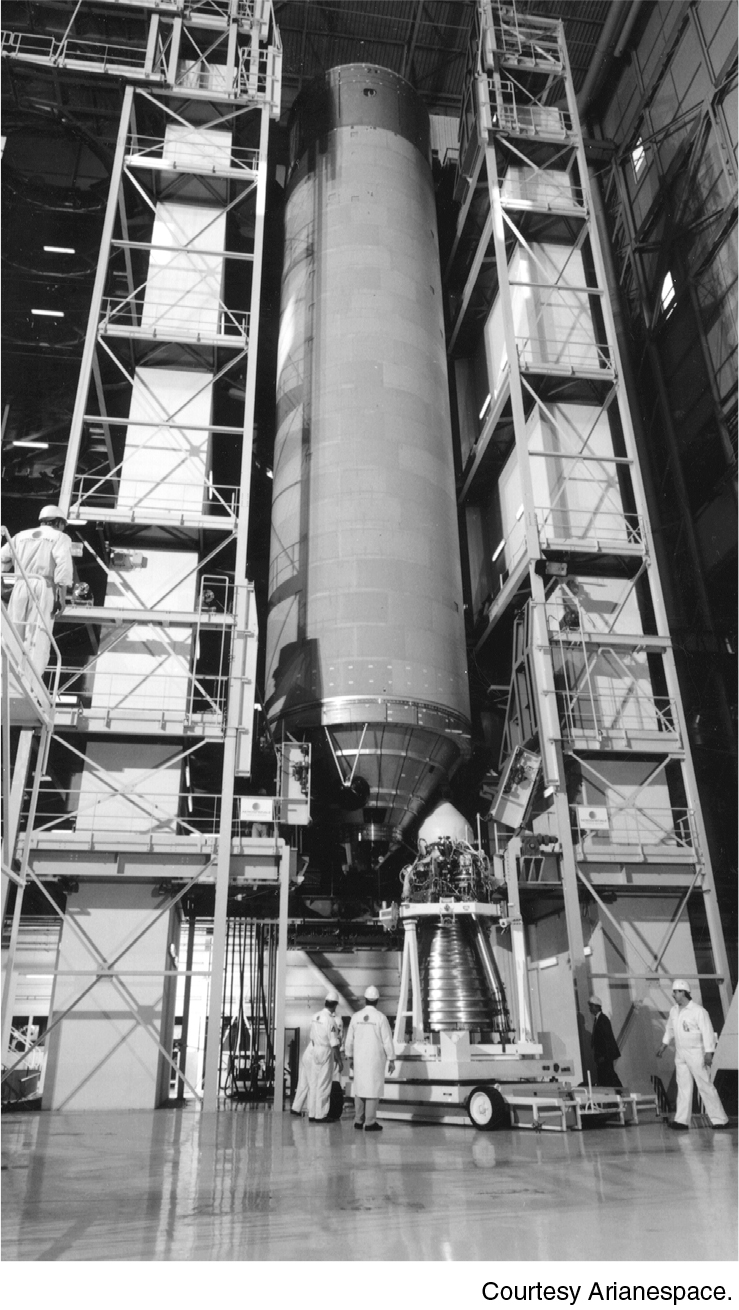
The EPC H173 core stage is a cryogenic stage powered by the Vulcain 2.1 main engine. The stage consists of two aluminum propellant tanks sharing a common hemispherical bulkhead. A thrust frame transmits the thrust of the main engine and solid boosters to the core stage structure. At the top of the stage, the forward skirt provides the interface to the second stage, and to the upper attachment points of the boosters. The forward skirt also includes most of the first-stage avionics.
The Vulcain 2.1 has a higher mixture ratio, 20% more thrust, and a larger nozzle than the Vulcain 1. The LOX turbopump has been redesigned to accommodate the higher flow rate of LOX. The main combustion chamber has been redesigned with a wider throat and new injector. Whereas the Vulcain 1 dumped the exhaust from the gas generator overboard, the Vulcain 2 injects the exhaust gas into the nozzle at an area ratio of 32:1, using it to film-cool the lower extension of the nozzle. For this reason, hydrogen cooling tubes are only required above this point, and the lower nozzle section is a single wall with stiffening rings. As a result of the increased thrust of the Vulcain 2.1, reinforcement of the thrust structure, engine gimbal system, some tank panels, and the front skirt was required. No changes to the feedlines were required, thanks to an increase in LOX turbo-pump suction and slightly higher tank pressure.
The ESC-A is a small, LOX/LH2 upper stage that is used for orbital injection. It is powered by a HM7B regeneratively cooled gas generator engine generating 62.2 kN (13.98 klbf) of thrust. It has no restart capability: the engine is continuously fired for 950 seconds in its Ariane 5 ECA version.
Ariane 5 Cryogenic Stage
ARIANE 5
EAP Booster P241 Ariane 5ECA | EPC Core Stage H173 Ariane 5ECA | |
Dimensions | ||
Length | 31.6 m (103.7 ft) | 23.8 m (78 ft) |
Diameter | 3.05 m (10.0 ft) | 5.4 m (18 ft) |
Mass (each) | ||
Propellant Mass | 240.2 t (530 klbm) | 170.0 t (374.8 klbm) |
Inert Mass | 40.3 t (89 klbm) | 14.7 t (32.4 klbm) |
Gross Mass | 280.5 t (618 klbm) | 184.7 t (407.2 klbm) |
Propellant Mass Fraction | 0.86 | 0.92 |
Structure | ||
Type | Monocoque | Semi-monocoque |
Material | Steel | Aluminum |
Propulsion | ||
Engine Designation | MPS (Europropulsion) | Vulcain 2 (Snecma) |
Number of Engines | 2 (3 field segments each) | 1 |
Propellant | HTPB | LOX/LH2 |
Thrust | Average: 5060 kN (1140 klbf) | Sea level: 960 kN (220 klbf) |
Vacuum Isp | 275.4 s | 429 s |
Chamber Pressure | 61.3 bar (890 psi) | 117.3 bar (1701 psi) |
Nozzle Expansion Ratio | 10.36:1 | 58.2:1 |
Propellant Feed System | Open-cycle gas generator turbopump | |
Mixture Ratio (O/F) | — | 6.1:1 |
Throttling Capability | No | 100% only |
Restart Capability | No | No |
Tank Pressurization | — | Fuel: Cold GH2 |
Attitude Control | ||
Pitch, Yaw | Hydraulic nozzle gimbal, ±6 deg | Blowdown hydraulic gimbal, ±6 deg |
Roll | Hydraulic nozzle gimbal, ±6 deg | ACS on VEB or upper stage |
Staging | ||
Nominal Burn Time | 129 s | 540 s |
Shutdown Process | Burn to depletion | Command shutdown |
Stage Separation | 8 separation rockets | Pyrotechnic tube and actuators |
ARIANE 6
LOX/LH2Booster P120 | Core Stage Vulcain 2.1 | Upper Stage Vinci | |
Dimensions | |||
Length | 11.7 m (38.4 ft) | 23.8 m (78 ft) | |
Diameter | 3.4 m (11.2 ft) | 5.4 m (18 ft) | 5.4 m (18 ft) |
Mass (each) | |||
Propellant Mass | 143.6 t (317 klbm) | 170.0 t (374.8 klbm) | 31.0 t (68.3 klbm) |
Inert Mass | 11 t (24 klbm) | 14.7 t (32.4 klbm) | |
Gross Mass | 154.6 t (341 klbm) | 184.7 t (407.2 klbm) | |
Propellant Mass Fraction | 0.93 | 0.92 | |
Structure | |||
Type | Monocoque | Semi-monocoque | Semi-monocoque |
Material | Steel | Aluminum | Aluminum |
Propulsion | |||
Engine Designation | P120C (Avio) | Vulcain 2.1 (Snecma) | Vinci |
Number of Engines | 1 | 1 | 1 |
Propellant | Aluminum-HTPB | LOX/LH2 | LOX/LH2 |
Thrust | Average: 4500 kN (1012 klbf) | Sea level: | Vacuum: 180 kN (40.5 klbf) |
Vacuum Isp | 278.5 s | 431 s | 457 s |
Chamber Pressure | 61.3 bar (890 psi) | 118.8 bar (1723 psi) | 60.8 bar (882 psi) |
Nozzle Expansion Ratio | 10.36:1 | 58.5:1 | 240:1 |
Propellant Feed System | — | Open-cycle gas generator turbopump | Expander cycle turbopump |
Mixture Ratio (O/F) | No | 6.03:1 | 6.1:1 |
Throttling Capability | No | 100% only | 100% only |
Restart Capability | — | No | No |
Tank Pressurization | Fuel: Cold GH2 | Fuel: Cold GH2 | |
Attitude Control | |||
Pitch, Yaw | Hydraulic nozzle gimbal, | Blowdown hydraulic gimbal, ±6 deg | Blowdown hydraulic gimbal, ±6 deg |
Roll | Hydraulic nozzle gimbal, ±6 deg | ACS on VEB or upper stage | ACS on VEB or upper stage |
Staging | |||
Nominal Burn Time | 132.8 s | 540 s | ? |
Shutdown Process | Burn to depletion | Command shutdown | Command shutdown |
Stage Separation | 8 separation rockets | Pyrotechnic tube and actuators | Pyrotechnic tube and actuators |
ARIANE 62
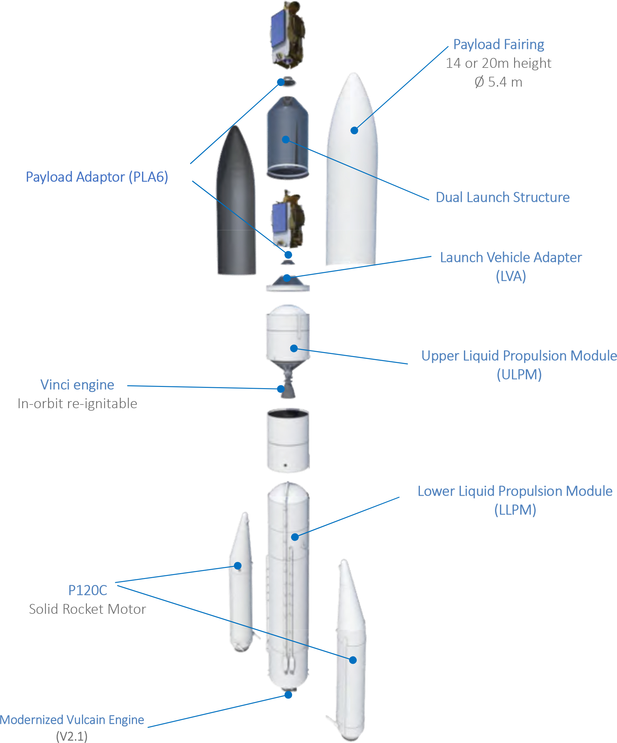
Ariane 62
ARIANE 64
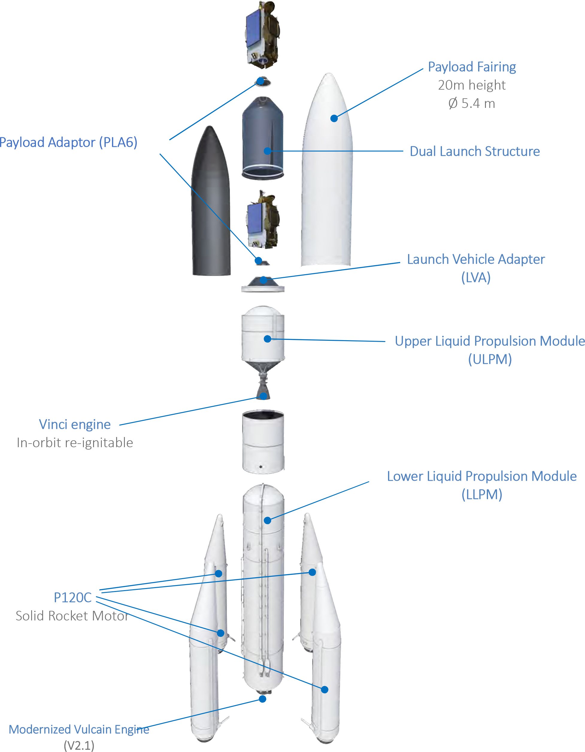
Ariane 64
Ariane 5 Upper Stages
The EPS is a small, storable propellant upper stage that is used for orbital injection. It is a relatively simple design, using a pressure-fed, gimbaled Aestus engine. Propellant is stored in four tanks pressurized by helium bottles. While the Aestus engine itself is restartable, the original EPS stage did not support engine restarts, because of limitations of thermal, power, and attitude control systems. Restart capability will be added for the “Versatile” version of the stage by upgrading these systems. The stage has also been upgraded by slightly increasing the amount of fuel that can be carried, and reducing the structural weight.
The EPS stage is encircled by the Vehicle Equipment Bay (VEB). The VEB is a short, ring-shaped structure that supports the fairing at the top of its outer circumference and the EPS on its inner circumference. The VEB contains the primary vehicle avionics as well as a hydrazine ACS. As part of a weight reduction program, the metal structure of the VEB has been replaced by carbon composite.
In response to growth in satellite mass, Arianespace and ESA chose to develop two new cryogenic upper stages for the Ariane 5E. The first is the ESC-A (Etage Supérieur Cryotechnique, cryogenic upper stage, Type A). To field a new cryogenic stage quickly, the ESC-A is derived from the successful Ariane 4 H10-3 stage, using the same HM-7B engine, a derivative 2.5-m diameter LOX tank, and a number of modified components, such as the thrust structure and the enlarged helium tank. While many elements could be reused, requalification was required to adjust to the longer burn duration, colder interstage environment, and different launch pad operations. A new 5.4-m diameter, 11.4-m3 (403-ft3) hydrogen tank was developed, using bulkheads similar to those on the EPC stage. The lower bulkhead is concave, allowing the LOX tank to nest within the hydrogen tank, though they do not share a common bulkhead. The two tanks are connected by 36 struts and 4 dampers. The upper stage is mounted on a new carbon composite interstage structure built by CASA.
Although the ESC-A could be developed quickly, it is considered only an intermediate step toward a more capable upper stage. The ESC-B will increase GTO performance from 10 t to 12 t, and also provide the capability for engine restarts. This requires the development of a new engine, which could not have been accomplished in time for the ESC-A. A key design decision during development was how to meet the needs of both GTO and so-called “versatile” missions, which can required different helium supplies, thermal insulation, and venting, depending on mission duration and the required number of engine starts. One option was to develop two slightly different versions of the stage—one optimized for GTO missions, the other for other missions. The second option was to design and build one flexible stage that could do both types of missions. The third option was to design the stage for GTO missions, with additional kits available to add capabilities as needed. The first option provides the best capability, but is the most expensive to develop. The second sacrifices some performance and is the most expensive to build. Considering the challenging cost and capability requirements and the prevalence of GTO missions, the third approach was selected.
The first ESC-B design, designated B0, had 23 t of propellant in two nested, but separate, propellant tanks. This design was reworked to achieve the performance and cost goals of the program. Keeping the propellant tanks separate would have simplified pressurization, but is heavier than common bulkhead tanks. A concept dubbed “stage under fairing” was considered, in which the entire stage would fit inside the payload fairing. This has weight advantages because the tanks do not need to support the aerodynamic loads of the fairing during flight, but loading propellant on the ground is difficult. The selected design, called B5-A H28, has 28 t of propellant in a common bulkhead tank, with the payload fairing above the stage. Essentially, there is a single propellant tank divided into two compartments. The hydrogen compartment is the same shape as the ESC-A tank, with a longer cylinder section. The oxygen is carried in a compartment formed by enclosing the lower concave cavity of the hydrogen tank. The engine for the ESC-B is the new Vinci engine developed by Snecma. It is an expander cycle engine capable of multiple restarts. For increased specific impulse, the engine has a large carbon–carbon nozzle extension skirt which is deployed in flight.
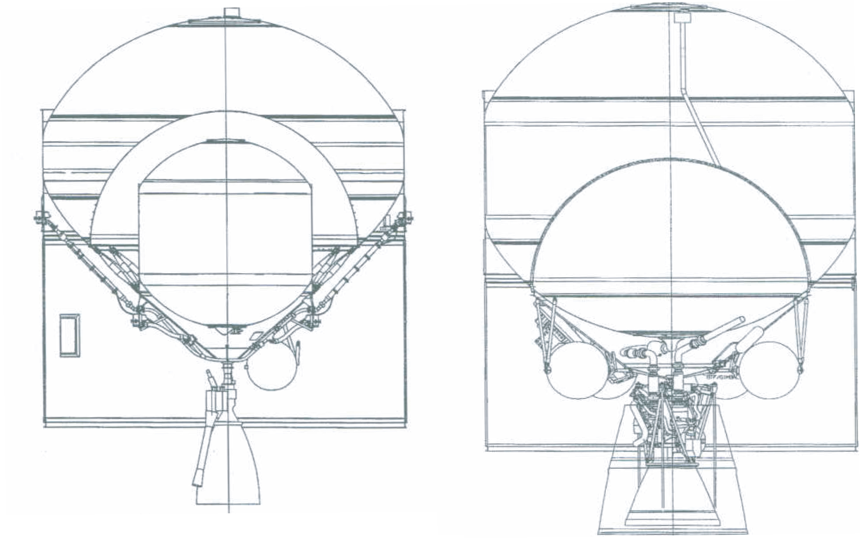
The ESC-A, left, and ESC-B, right, upper stages
A VEB is mounted above each stage. The Ariane 5G VEB has a height of 1.56 m (5.1 ft), diameter of 5.46 m (17.9 ft), and mass of 1500 kg (3300 lbm). For Ariane 5E an upgraded VEB is used with a lightweight composite structure and the ACS thrust package may be deleted in favor of using the thrusters on the ESC-A upper stage. This VEB has a mass of 950 kg (2100 lbm) and a height of 1.13 m (3.7 ft).
ESC-A | |
Dimensions | |
Length | 4.71 m (15.5 ft) |
Diameter | 5.43 m (17.8 ft) |
Mass (each) | |
Propellant Mass | 2590 kg LH2 + 11,950 kg LOX (5710 + 26,435 Ibm) |
Inert Mass | 3418 kg (7535 Ibm) |
Gross Mass | 17,958 kg (39,590 Ibm) |
Propellant Mass Fraction | 0.81 |
Structure | |
Type | Monocoque tanks, struts for intertank structure |
Material | Aluminum |
Propulsion | |
Engine Designation | HM7B (Snecma) |
Number of Engines | 1 |
Propellant | LH2/ LOX |
Average Thrust | 64.8 kN (14.6 klbf) |
Isp | 445.5 s |
Chamber Pressure | 35 bar (508 psi) |
Nozzle Expansion Ratio | 83:1 |
Propellant Feed System | Gas-generator cycle turbopump |
Mixture Ratio (O/F) | 4.86:1 |
Throttling Capability | 100% only |
Restart Capability | No |
Tank Pressurization | Fuel: GH2 |
Attitude Control | |
Pitch, Yaw | Nozzle gimbal, Cold-gas hydrogen thrusters |
Roll | Cold-gas hydrogen thrusters |
Staging | |
Nominal Burn Time | 970 s |
Shutdown Process | Command shutdown |
Stage Separation | 4 acceleration rockets |
Attitude Control System
Ariane 5
The solid boosters are equipped with a blowdown hydraulic nozzle gimbal system (GAT), which enables pitch, yaw, and roll control. The core stage is equipped with a hydraulic engine activation system (GAM), which enables swiveling of the Vulcain engine for pitch and yaw control. The 180-liter (47-gal) hydraulic system is an open-cycle system pressurized by helium. An electromechanical gimbal on the Aestus engine provides pitch and yaw control during flight of the EPS second stage. After separation of the solid boosters, roll is controlled by a hydrazine attitude control system (SCA) installed in the VEB. This system also provides three-axis control during coast periods and deployment maneuvers. The SCA is a blowdown hydrazine system pressurized by nitrogen, with thrust levels decaying from 200 to 100 N (45 to 22 lbf). The cryogenic upper stages use nozzle gimbaling to control pitch and yaw during thrusting phases. Roll control during burns and three axis control during coast phases are provided using thrusters powered by hydrogen tapped from the main fuel tank.
Avionics
Ariane 5
Navigation data are provided by two redundant strap-down Inertial Reference Systems (IRS). Each IRS contains three ring laser gyros and four accelerometers. The IRS units are very similar to the Ariane 4 system to maintain reliability and reduce development cost. However, the failure of the maiden flight of Ariane 5 was caused by a data type conversion error in the IRS software, which occurred because the Ariane 5 trajectory profile causes some navigation parameters to exceed values experienced on Ariane 4. IRS data are provided to the onboard computer (OBC), which calculates guidance commands and event timing. The Ariane 5 VEB also contains the telemetry systems, redundant batteries and power distribution systems, and a flight termination system.
Payload Fairing
Ariane 5
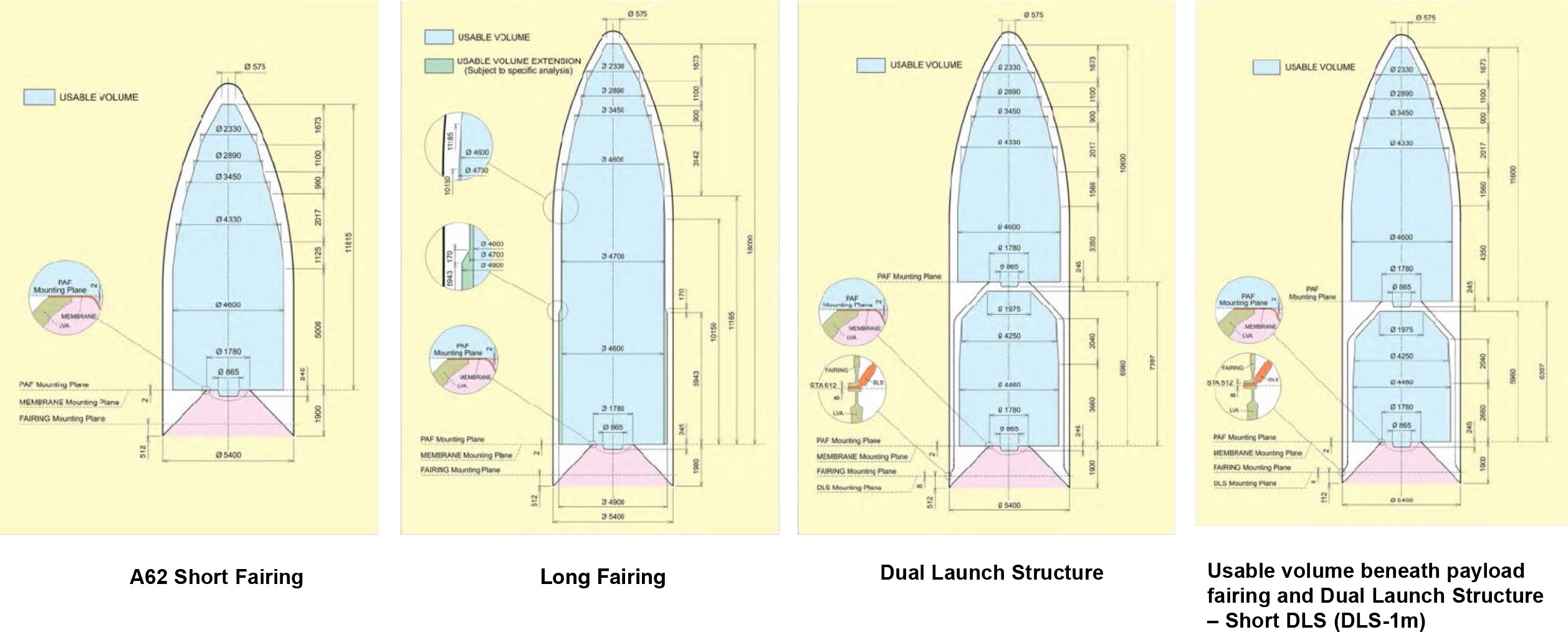
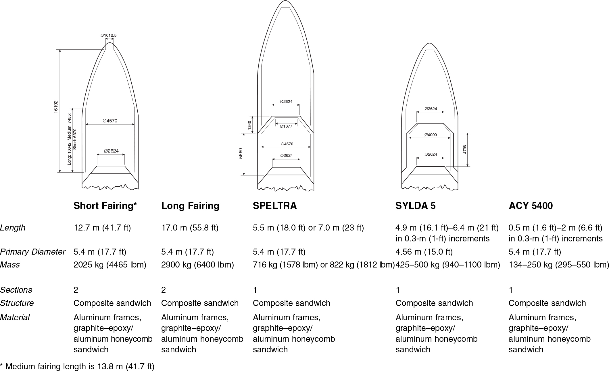
Ariane 5 is designed to launch two comanifested payloads per flight. This requires a significant amount of flexibility to ensure that the volumetric requirements of any combination of satellites can be met. Four different elements, each available in several lengths, can be combined to provide a large number of possible combinations.
The primary element, the payload fairing, has a 5.4-m (17.7-ft) outer diameter. It is available in short, medium and long lengths. The fairing structure is made up of sandwiched panels with an aluminum honeycomb core between CFRP skins. It is a two half-shell structure with a longitudinal separation system similar to that used on Ariane 4. The horizontal separation system is located in the lower flange and is based on a pyrotechnic cord. The long fairing is made of two parts, the upper one being similar to the short fairing, while the lower part is an extension. Acoustic absorbers are standard.
The Speltra is an external support structure providing an extra compartment for dual launches. It is made up of a 5.4-m (17.7-ft) diameter cylinder, which sits between the VEB and the fairing, and a conical section, which supports the upper payload. The lower payload is carried inside the Speltra. The Speltra is available in two versions, Speltra 4160 and Speltra 5660, indicating the length of the cylindrical compartment in millimeters. The structure is made of sandwiched panels with an aluminum honeycomb core between CFRP skins. The lower flange of the Speltra contains a pyrotechnic separation system. Doors are available in both the Speltra and fairing.
The Sylda 5 is also a dual-payload compartment, but unlike the Speltra it is a smaller 4.5-m (15.0-ft) diameter structure that fits inside the payload fairing. While it can not carry large diameter satellites internally, it weighs much less than a Speltra because it does not have to support fairing aerodynamic loads during ascent. The basic Sylda 5 can also be extended up to 1.5 m (4.9 ft) in 0.3-m (1-ft) increments.
A 5.4-m diameter spacer element, the ACY 5400, is available in lengths from 0.5 to 2.0 m (1.6–6.6 ft) in 0.5-m (1.6-ft) increments. It is simply a cylindrical ring spacer that can be used to vary the payload compartment height of any of the elements described above.
ARIANE 5
ARIANE 6
